Mechanical Assembly
Overview
The robot’s structure is an adaptation of unmanned vehicles that monitor the surface of Mars and the moon. It features a Rocker-Bogie suspension made of aluminum profile, developed in 1996 for NASA’s Sojourner rover. This suspension system keeps the chassis level even on uneven terrain, minimizing rolling and pitching.
The suspension consists of two axles:
The first axle is fixed to the chassis and rotates the larger arm (rocker).
The second axle is at the end of the first and rotates the smaller arm (bogie).
Wires from the motors and encoders pass through these axles to the inside of the chassis.
Chassis Design
The robot’s chassis is composed of:
Aluminum bars
Acrylic sheets
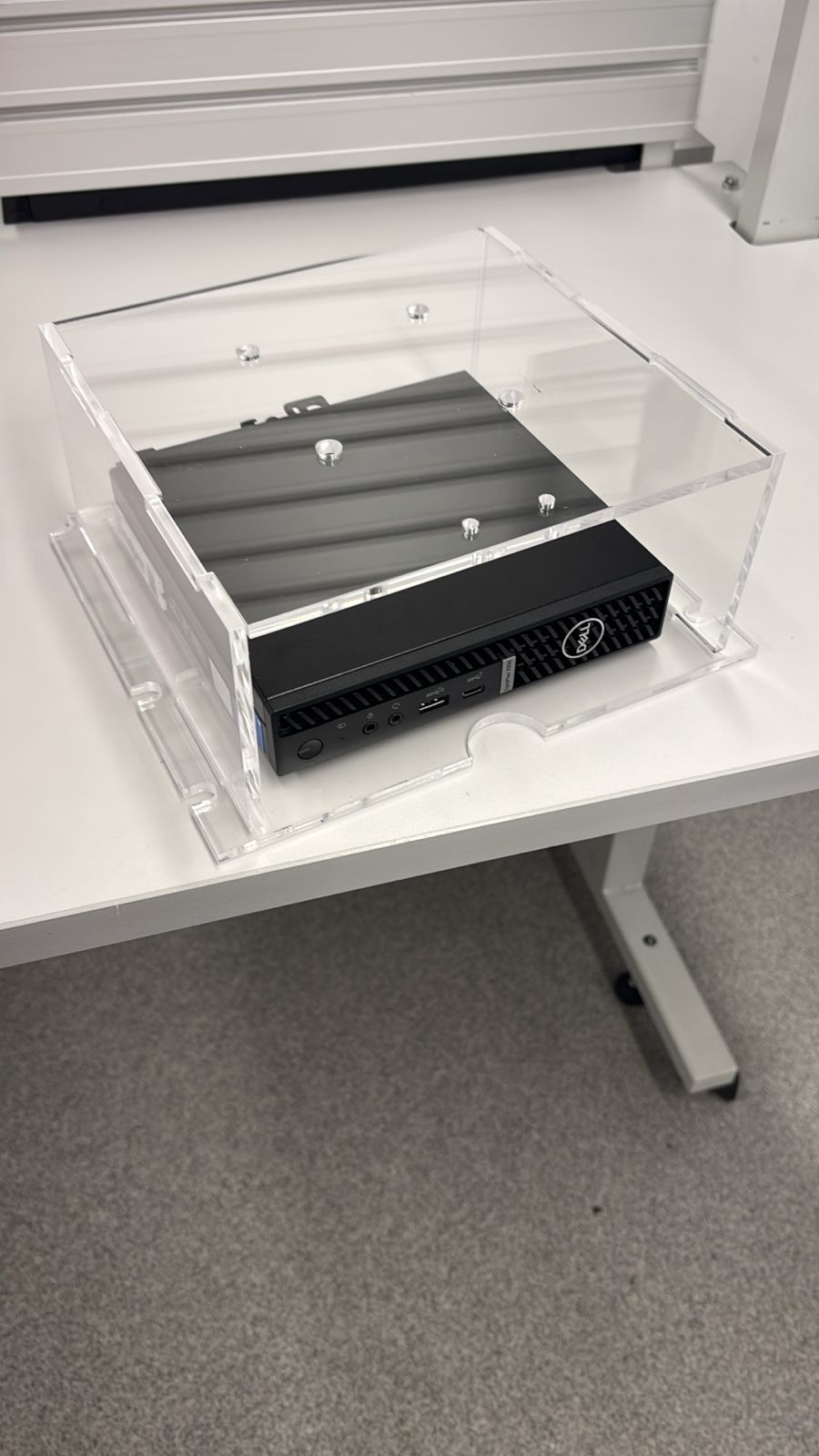
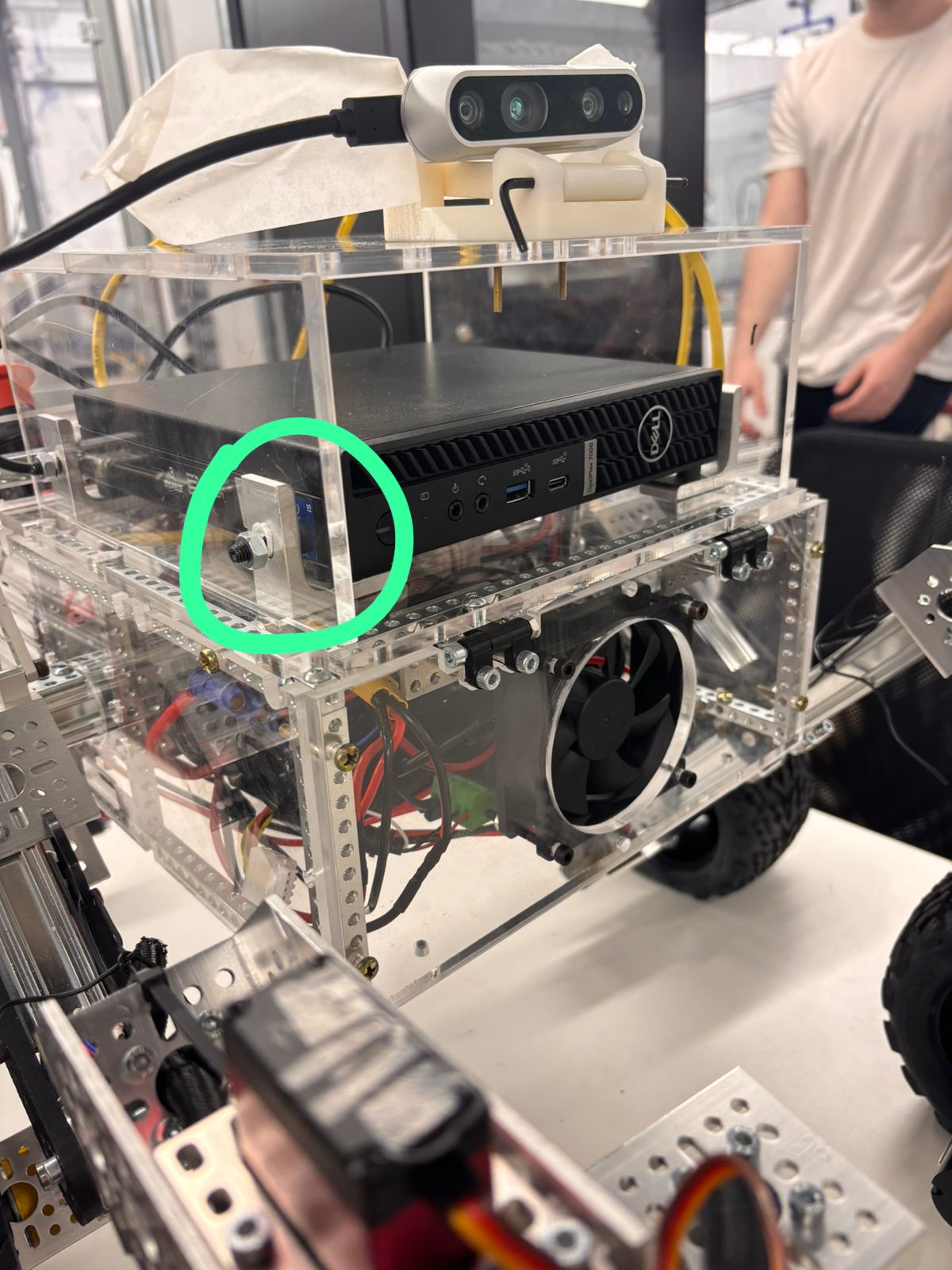
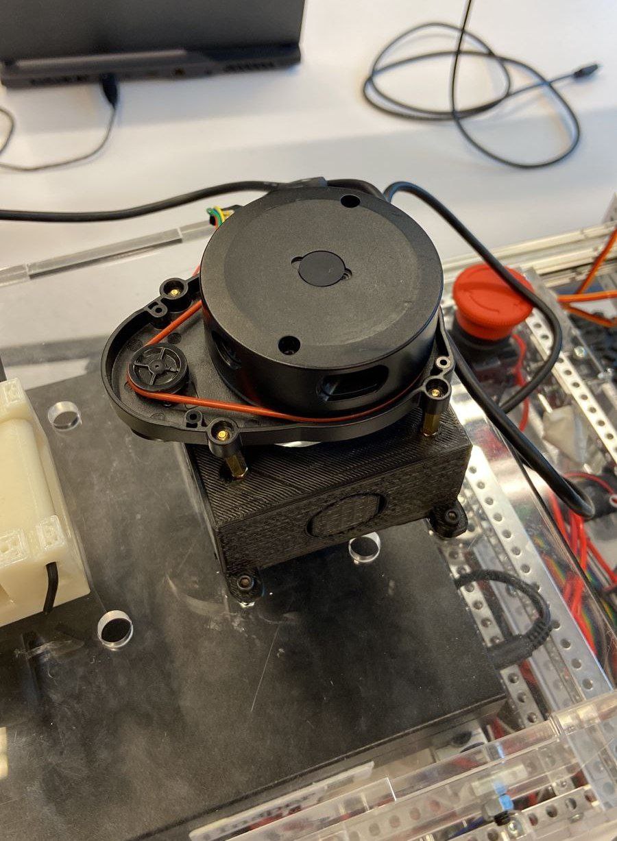
These components house the device’s electronic boards, batteries, and HMI. Camera and LiDAR supports are attached to the chassis.
Design Considerations:
The robot’s center of mass is positioned above the unsprung mass (wheels and suspension) for greater stability.
Maximum incline is limited to angles less than 45° due to the height of the center of mass.
Obstacles exceeding the combined torque of the six motors or with a height greater than the wheel radius cannot be overcome.
Assembly Instructions
For detailed instructions on base assembly, including the main body frame and rocker-bogie suspension, refer to the Open Source Rover official docs: https://github.com/nasa-jpl/open-source-rover/tree/master/mechanical.
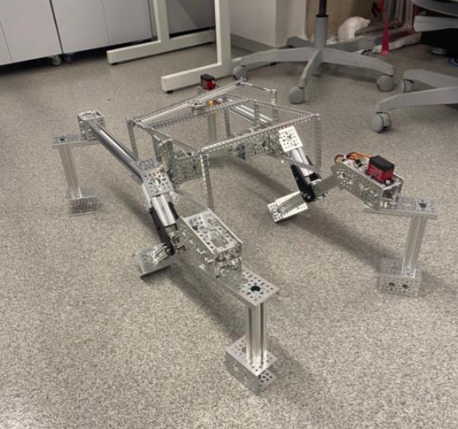
Base structure.
Wheel assembly subsystem: https://github.com/nasa-jpl/open-source-rover/blob/master/mechanical/wheel_assembly/README.md
Main body subsystem: https://github.com/nasa-jpl/open-source-rover/blob/master/mechanical/body/README.md
Rocker-Bogie suspension subsystem: https://github.com/nasa-jpl/open-source-rover/blob/master/mechanical/rocker_bogie/README.md
Component Adaptations
Some parts may need adaptation based on component availability:
Aluminum Profiles
If 96 mm profiles are unavailable:
Purchase larger profiles and cut to the correct dimension.
Redo threading for M4 screws in all four holes of each cut part.
Use taps of different sizes in three stages to achieve the desired thread size.
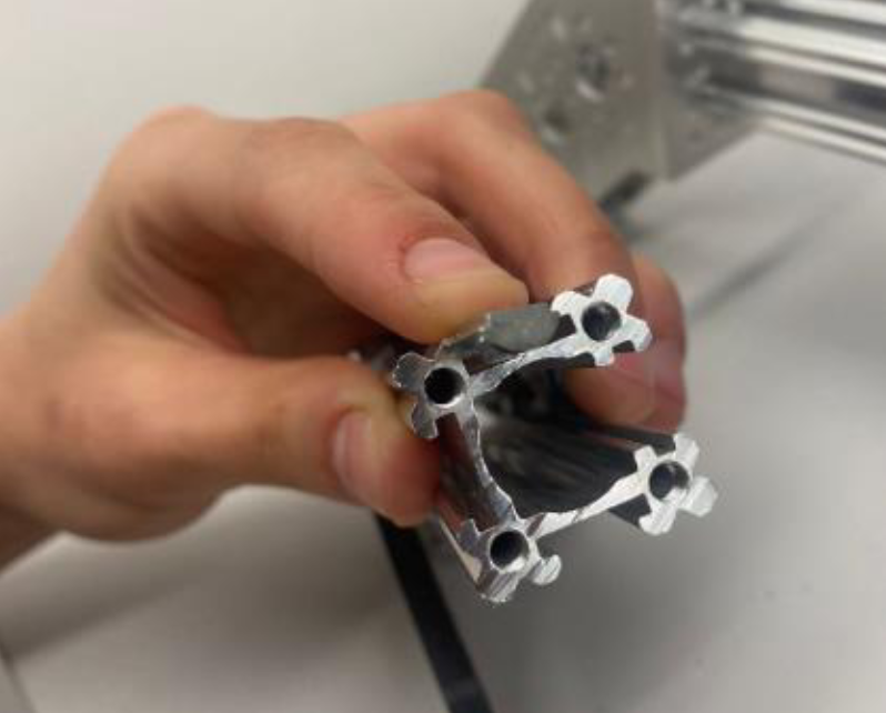
Cut aluminum profile.
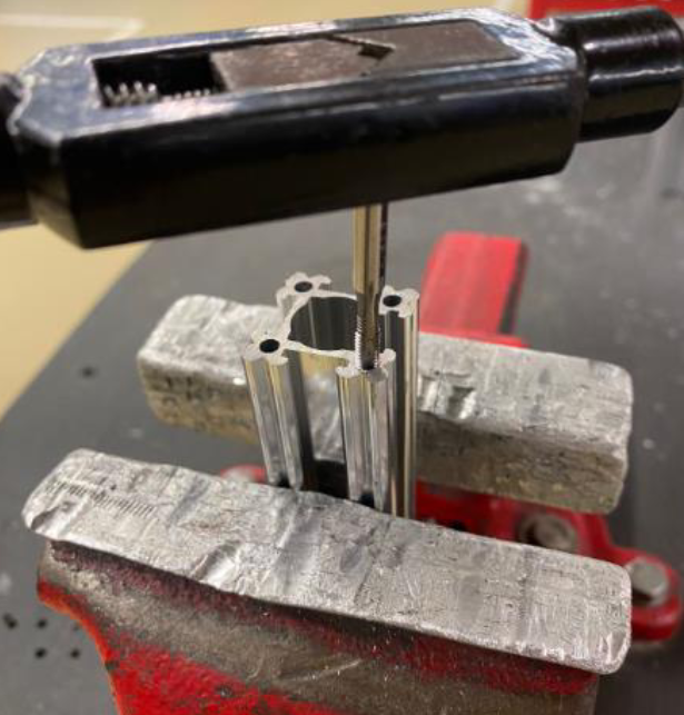
Threading operation.
Drilling Operations
After cutting the parts, it may be necessary to drill the bars, since the existing hole may not be through like in the profile. In addition, it may also be necessary to perform threading in two stages, as was the case with the other part mentioned above.
If drilling is necessary, follow these steps:
Paint the face to be drilled with a marker.
Mark the hole center using a vertical height marker.
Create a central mark using a center punch, vice, and hammer.
Drill using a manual benchtop milling machine, ensuring proper alignment and chip evacuation.
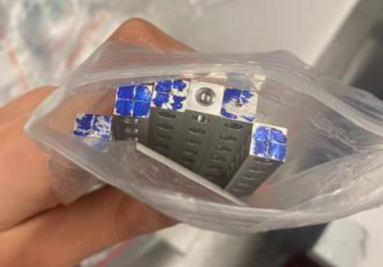
Marking for drilling operation.
Bearing Substitution
If the original bearing part is unavailable:
Use a substitute with an equivalent internal diameter.
Note that slight structural deformation may occur but should not compromise operation.
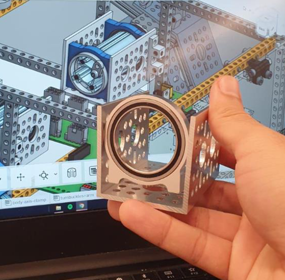
Substitute bearing.
Wheel Fixation
Due to the torque of the engines, it may be necessary to modify the wheel attachment.
Originally, the attachment is established between the engine shaft and the wheel with a central screw pressing the wheel between a washer and the wheel hub attached to the engine shaft. After the new attachment, the wheels are drilled and attached, with two screws each, to the wheel hubs. However, it was found that this strategy, suggested in the official project repository, is prone to misalignment.
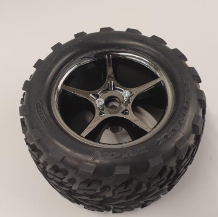
Example of attaching the wheel to the hub
Note
As of the writing of this document, there is an error in the official documentation:
Component initially coded as 1601 actually corresponds to component number 1611.
The 3D assembly view shows a part with an internal diameter less than 8 mm, which does not fit the specified axle.
